
The purpose software design instructions are designed for ultra-large indoor navigation. Computer technology is evolving, and it is becoming more and more widely used in various industries.
Purpose of Writing
This software design manual is designed for ultra-large indoor navigation. Computer technology is evolving rapidly and is being used increasingly in a variety of industries. This size, complex design and heavy human traffic in rooms such as the Rainbow Bridge hub, large exhibitions or Wanda Square, will inevitably prevent people from finding a destination route, and the development of indoor navigation machines will make it easier for people to travel, shop and wander, free people from traditional navigation methods, improve efficiency and help people to understand information about the indoor environment.
[[heading]]
[[/heading]]
2. Overall development ideas
The user enters the destination and the machine starts navigation
The navigation robot keeps taking pictures as it moves forward
Photos are sent to the background for processing
The system will determine the location of the robot according to the characteristics of the picture.
The system indicates the most recent route from the current location to the destination, depending on where the user enters it
System development steps:
- Clarify Requirements
- Design database
- Design technical framework
- Java technology
- Data access layer
- Operation sequence
System Startup
User Operation
Backend operations
Operation Successful
3. Design requirements
3.1 Overview of project requirements:
The system records every route in the room, and there's congestion or other accidents that can be added and removed.
The user can enter the address or destination information and the system will reach the destination according to the best route chosen by the user
Users can cancel navigation at any time
After the navigation is completed, the machine will arrive at the designated location.
3.2 Navigation technical requirements
- Advancedity: the introduction of advanced and mature technology to ensure the advanced, economic and practical nature of the system.
- is safe and reliable.
- Regulatory: Development process control, development of technology, system coding, documentation should be standardized and followed appropriate national and international standards.
- Reliability: to ensure the reliable operation of the system and ease and speed of upgrading.
- Expansion: The system should be able to adapt, add or decrease functions, upgrade modules, and progressively improve the system architecture, depending on the changes in demand.
- Maintainability: System maintenance should be simple.
3.3 Interface design requirements
(1) Uniformity principle
①Unified interface style
Display the same type of data in the same way, e.g. date type
②Uniform interaction style
Do the same type of operation in the same way, e.g., enter date
(2) Principle of aesthetics
Beautiful and elegant interface
Ease of use principle
The process of identification is to be safe and to be as simple as possible.
4. Module structure
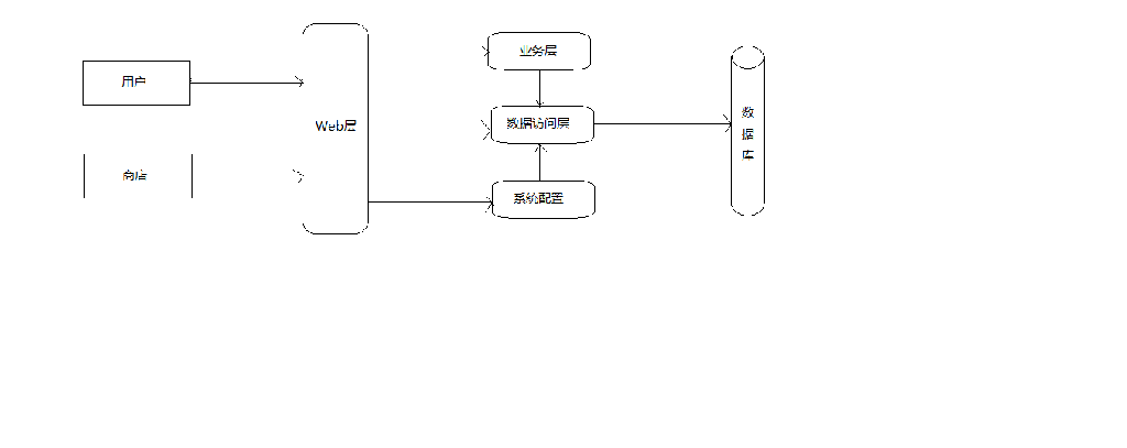
The entire system is divided into three parts: a positioning module, a user client and a server module in the back. The positioning module transmits position information to a back-end server, where the back-end server analyzes the appropriate route, as shown in the chart above. The server software design is based on the JAVA language and MySQL databases, which are used primarily to receive, store, store and send data uploaded in the positioning module and the user client software, as well as to request accordingly and to send the data to the client.
[[heading]]
[[/heading]]
4.1 Positioning module and client module
The real-time positioning module, which allows the client to receive off-the-shelf loop access to the server through data, uses POST to obtain real-time location information for the user, and then interprets the data and displays it on the user interface. The section allows for the user ' s current location, destination location and codiscretion on the map interface. Leaves the interface to close the data acquisition thread and location to prevent the memory from being occupied.
4.2 Backend server
The anomaly detection function and data acquisition are performed in the backstage Service, which also accesss the server every 5min to obtain data on the current location of the user.
5. System structure and function
5.1 Overall structure
Overall class diagram
5.2 System architecture
5.3 System operation process
5.3.1 System startup
When the user enters the interior, the user has a system start-up module: display the interior panorama, current location information at system start-up. Upon system start-up, hint to enter the destination or relevant information.
5.3.2 Generate route
After landing on the module, the user enters the destination or the relevant information, the system determines whether the destination exists and, if it exists, output the best route and prompts the selection of the corresponding operation to start the navigation. If the commodity does not exist, alerts the user and returns to the user's initial interface. We use the example of presence where the user clicks to start the navigation, the robot starts the navigation according to the route generated. The user can cancel the navigation while en route, and the machine returns to its initial position for use by other users.
5.3.3 Robot navigation process
When robots successfully begin to navigate, they choose the best route forward, while taking photographs for system processing, which determines the current position of robots based on their photo characteristics (current location characteristics and photo angles, etc.) and guides robots to move. Navigation successfully shows hints.
5.3.4 Navigation successful
When the user is successfully navigating, the robot returns to its initial position for other users.