
Introspective 1 for dust instrument development, this instrument is a light-scattered rapid dust detector with a range of cutters available, an internal filter sampling device, which can...
Dust meter development and design instructions
1 Introduction
This instrument is a light-dispersible rapid dust detector with a range of cutters available for choice, and contains a filter sampling device that collects dust samples while continuously monitoring particulate matter in the air for composition analysis and the application of the membrane graft method to find a K-conversion factor. The PMS5XXXS series is a dual sensor that monitors both particulate and formaldehyde concentrations in the air. The monitoring of particulate concentrations is based on the laser dispersion principle, which allows the number of suspended particles of different particles in the air in a unit of volume to be collected and calculated, i.e. the distribution of particulate concentrations, and thus converted to a mass concentration. The monitoring of formaldehyde concentrations is based on electrochemical principles, with high accuracy and stability. This sensor can be embedded in various instruments related to air quality monitoring and improvement, providing timely and accurate concentration data. This instrument applies to rapid determination of concentrations of inhalable particles in public places, detection of PM10 and PM2.5 concentrations in central air-conditioning vents, detection of industrial and industrial production sites, monitoring of inhalable dust concentrations in the field of environmental protection, and evaluation of the efficiency of air purification units.
The main purpose of this design note is to provide the designer concerned with the product with an explanation of the design thinking and code of the control software, so that existing codes can be maintained and further refined and new functions added to the existing ones.
Project background:
The project primarily addressed the detection of concentrations of dust in air (mainly PM10 and PM2.5) and provided timely and accurate concentration data to clients.
Definition:
u16 PM25value A - Defines the instant PM2.5 value
N 50——50 times per channel
M 4 - for 4 channels
Currenzeropoint -- current zero
u8 index of recbufferIndex - rec buffer
workMode - working mode
AD Value[N] [M] -- used to store ADC conversions and is the DMA's target address
After filter[M] - Results after storage of averages
Mission overview
The PMS5XXXS series is a two-part sensor that monitors both particulate and formaldehyde concentrations in air. The monitoring of particulate matter concentrations is based on laser dispersion principles that allow the number of suspended particles of different particles in the air in a unit of volume to be collected and calculated continuously, i.e., their concentration distribution, and thus converted to a mass concentration. The monitoring of formaldehyde concentration is based on electrochemical principles and has high accuracy and stability. The concentration values for particulate matter and formaldehyde are combined to be exported in the form of a generic digital interface. This sensor can be embedded in various instruments related to air quality monitoring and improvement and provide timely and accurate concentration data.
Requirements overview
This instrument is to be applied to the rapid determination of inhalable particulate concentrations in public places, the testing of PM10 and PM2.5 concentrations in central air-conditioning vents, the detection of industrial and mining production sites, the monitoring of inhalable dust concentrations in the field of environmental protection, and the evaluation of the efficiency of air purification units.
- 2 Conditions and limitations
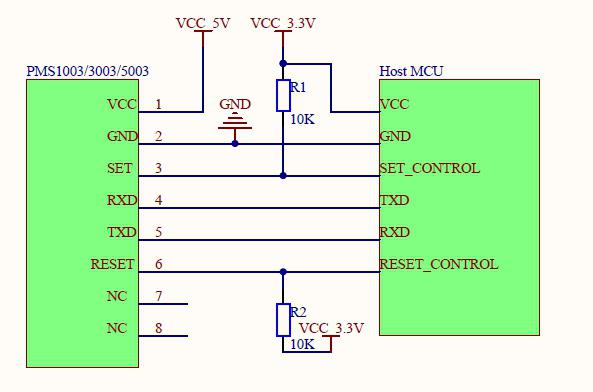
PMS 50003 requires a 5V power supply, because wind engines require a 5V drive. But all other data communications and control tube feet require 3.3V as a high level of power. Therefore, the main board MCU connecting to it should be 3.3V. If the main board MMU is powered by 5V, a flat core or circuit should be added to the communication line (RXD, TXD) and the control line (SET, RESET). SET and RESET have up-to-date electrical resistance, which should be suspended if not used. PIN7 and PIN8 should be applied to suspend the circuit for internal application. Application of the hibernation feature should be careful that the fans stop working while they restart take at least 30 seconds of stable time, so that, in order to obtain accurate data, the hibernation awakening sensor should not work for less than 30 seconds.
Overall design
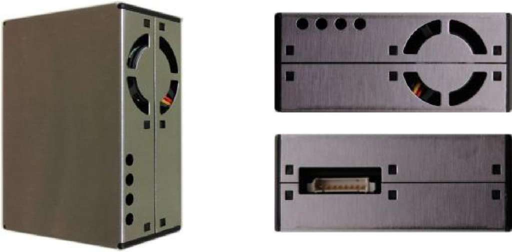
Main Features
The laser scattering principle achieves accurate measurement
Zero error alarm rate
Responds in real time and supports continuous collection
Minimum resolution particle size 0.3? m
New patent structure, six full-dimensional shielding, stronger resistance to interference.
The direction of the entrance and exit is optional, the scope of application is wide, and the user is no longer required to design the tunnel.
Can output formaldehyde monitoring data in real time
Working principle
This sensor uses the laser dispersion principle. This means that laser exposure to suspended particles in the air produces dispersions, while collecting dispersing light at a particular angle and obtaining a curve of dispersing light strength over time. Microprocessors then use algorithms based on the miE theory to arrive at equivalent particles of particles and the number of particles of different particles in a unit of volume.
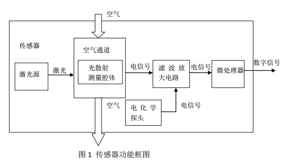
The formaldehyde monitoring function is implemented using electrochemical principles, incorporating data processing algorithms, and the data obtained are stable and accurate.
Technical indicators
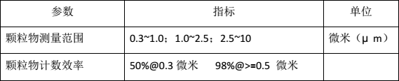
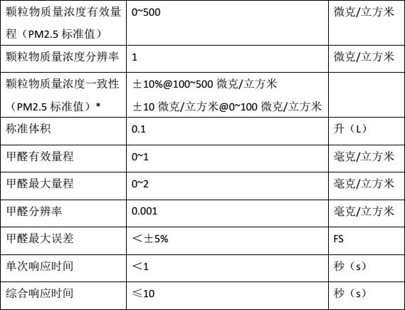
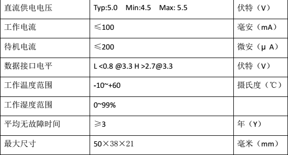
Note: Consistency data for particulate matter are data from the communication protocol (see appendix A).
20℃, humidity 50%
Digital interface definition
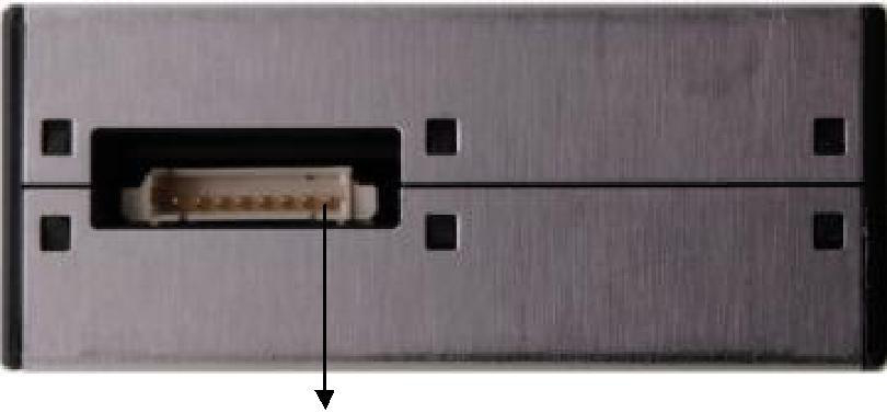
Figure 2 Interface schematic diagram
Pin Serial Number
Function label
Description
PIN1
VCC
Positive power supply (+5V)
PIN2
GND
Power supply negative
PIN3
SET
Set pipe foot / TTL level@3.3V, high level or suspended
Normal working state, low level is dormant state
PIN4
RXD
Serial receiver foot/TTL level@3.3V
PIN5
TXD
Serial Send tube foot/TTL level@3.3V
PIN6
RESET
Modular Recoup Signal/TTL level@3.3V, low compound
PIN7
NC
PIN8
NC
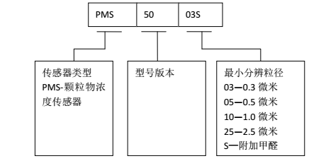
Model definition
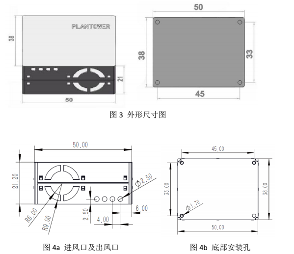
Size structure
Unit: mm
Serial port 1 initialization
void USART1_Configuration(void)
{
USART_InitTypeDef USART_InitStructure;
USART_ClockInitTypeDef USART_ClockInitStructure;
RCC_APB2PeriphClockCmd(RCC_APB2Periph_TIM1 |RCC_APB2Periph_USART1, ENABLE );
USART_ClockInitStructure.USART_Clock = USART_Clock_Disable;
USART_ClockInitStructure.USART_CPOL = USART_CPOL_Low;
USART_ClockInitStructure.USART_CPHA = USART_CPHA_2Edge;
USART_ClockInitStructure.USART_LastBit = USART_LastBit_Disable;
/* Configure the USART1 synchronous paramters */
USART_ClockInit(USART1, &USART_ClockInitStructure);
USART_ClockInit(USART2, &USART_ClockInitStructure);
USART_ClockInit(USART3, &USART_ClockInitStructure);
USART_InitStructure.USART_BaudRate = 9600;
USART_InitStructure.USART_WordLength = USART_WordLength_8b;
USART_InitStructure.USART_StopBits = USART_StopBits_1;
USART_InitStructure.USART_Parity = USART_Parity_No ;
USART_InitStructure.USART_HardwareFlowControl = USART_HardwareFlowControl_None;
USART_InitStructure.USART_Mode = USART_Mode_Tx|USART_Mode_Rx; /* Configure USART1 basic and asynchronous paramters */
USART_Init(USART1, &USART_InitStructure);
USART_Init(USART2, &USART_InitStructure);
USART_Init(USART3, &USART_InitStructure);
USART_ClearFlag(USART1, USART_IT_RXNE);
USART_ClearFlag(USART2, USART_IT_RXNE);
USART_ClearFlag(USART3, USART_IT_RXNE);
USART_ITConfig(USART1,USART_IT_RXNE, ENABLE);
USART_ITConfig(USART2,USART_IT_RXNE, ENABLE);
USART_ITConfig(USART3,USART_IT_RXNE, ENABLE);
USART_ITConfig(USART1, USART_IT_IDLE, ENABLE);
USART_ITConfig(USART2, USART_IT_IDLE, ENABLE);
USART_ITConfig(USART3, USART_IT_IDLE, ENABLE);
USART_ITConfig(USART1, USART_IT_ORE, ENABLE);
USART_ClearFlag(USART1, USART_FLAG_TC);
USART_ClearFlag(USART2, USART_FLAG_TC);
USART_ClearFlag(USART3, USART_FLAG_TC);
USART_Cmd(USART1, ENABLE);
USART_Cmd(USART2, ENABLE);
USART_Cmd(USART3, ENABLE);
}
When the clock is low-level, the clock is captured from the second edge until the clock pulse that captures the last data is not exported from SCLK, and the clock parameters are initialized when this activity is completed. We set this device to work with 9600.
Send received data
void mputs_1(char *p,u8 i)
{
while(i--)
{
/* Send one byte from USARTy to USARTz */
USART_SendData(USART1, *p++);
/* Loop until USARTy DR register is empty */
while(USART_GetFlagStatus(USART1, USART_FLAG_TXE) == RESET)
{
}
}
}
u16 GetPumpSumTime()
{
return parameter.totalpumptime;
}
u16 GetLaserSumTime()
{
return parameter.lasertotaltime;
}
s16 GetSPAN()
{
return
parameter.span25;
}
void StopDetect()
{
workMode=3;
}
void StartDetect()
{
workMode=4;
}
void SetPumpSpeed(u16 sp)
{
PumpSpeedbak=sp;
parameter.pumpspeed=sp;
saveParameterToFlash();
};
void SetCorrectMode(){ //correct mode
gtime=0; // clear the time counter ,gtime is count in mS
workMode=1;//setting the correct MODE tag
}
void PkgResponse(char *p,u8 num)
{ u32 i=2000;
PB9_H; //max485 DE=1 transmit mode
mputs_1(p,num);
while(i--);
PB9_L; //max485 DE=0 receive mode
}
The above code uses the following parameters:
RS-485 communication
Receive Commands
PM2.5 CPM value sending request
address
function
starting address Hi
starting address Lo
No. of points Hi
No. of points Lo
error check
01H
03H
00H
0DH
00H
01H
CRC16
PM10 CPM measurement result request
address
function
starting address Hi
starting address Lo
No. of points Hi
No. of points Lo
error check
01H
03H
00H
0CH
00H
01H
CRC16
SPM CPM determination request / 1000
address
function
starting address Hi
starting address Lo
No. of points Hi
No. of points Lo
error check
01H
03H
00H
01H
00H
01H
CRC16
Measurement stop request
address
function
starting address Hi
starting address Lo
preset data Hi
preset data Lo
error check
01H
06H
00H
03H
00H
00H
CRC16
- 1.4.1 Start of measurement
address
function
starting address Hi
starting address Lo
preset data Hi
preset data Lo
error check
01H
06H
00H
33H
00H
00H
CRC16
Pump running cumulative time to send request
address
function
starting address Hi
starting address Lo
No. of points Hi
No. of points Lo
error check
01H
03H
00H
24H
00H
01H
CRC16
Pump operating current sending request
address
function
starting address Hi
starting address Lo
No. of points Hi
No. of points Lo
error check
01H
03H
00H
14H
00H
01H
CRC16
Pump running speed sending request
address
function
starting address Hi
starting address Lo
No. of points Hi
No. of points Lo
error check
01H
03H
00H
04H
00H
01H
CRC16
Pump running speed setting request
address
function
starting address Hi
starting address Lo
No. of points Hi
No. of points Lo
error check
01H
06H
00H
04H
00H
01H
CRC16
Laser running cumulative time dispatch request in hours
address
function
starting address Hi
starting address Lo
No. of points Hi
No. of points Lo
error check
01H
03H
00H
05H
00H
01H
CRC16
BG measurement start request
address
function
starting address Hi
starting address Lo
preset data Hi
preset data Lo
error check
01H
06H
00H
06H
00H
01H
CRC16
BG measurement stop request
address
function
starting address Hi
starting address Lo
preset data Hi
preset data Lo
error check
01H
06H
00H
06H
00H
00H
CRC16
BG measurement result request
address
function
starting address Hi
starting address Lo
No. of points Hi
No. of points Lo
error check
01H
03H
00H
07H
00H
01H
CRC16
SPAN measurement start request
address
function
starting address Hi
starting address Lo
preset data Hi
preset data Lo
error check
01H
06H
00H
08H
00H
01H
CRC16
SPAN measurement stop request
address
function
starting address Hi
starting address Lo
preset data Hi
preset data Lo
error check
01H
06H
00H
08H
00H
00H
CRC16
SPAN measurement result request
address
function
starting address Hi
starting address Lo
No. of points Hi
No. of points Lo
error check
01H
03H
00H
09H
00H
01H
CRC16
K value setting request /1000
address
function
starting address Hi
starting address Lo
preset data Hi
preset data Lo
error check
01H
06H
00H
0AH
DATA1
DATA2
CRC16
K value query request
address
function
starting address Hi
starting address Lo
preset data Hi
preset data Lo
error check
01H
03H
00H
0BH
00H
01H
CRC16
1.1.22 Correction mode
address
function
starting address Hi
starting address Lo
preset data Hi
preset data Lo
error check
01H
06H
00H
0FH
00
00
CRC16
Command response
CPM value transmission request response
address
function
byte count
data Hi
data Lo
error check
01H
03H
02H
DATA1
DATA2
CRC16
CPM value measurement cycle setting response
address
function
register address Hi
register address Lo
preset data Hi
preset data Lo
error check
01H
06H
00H
02H
DATA1
DATA2
CRC16
Measurement stop request response
address
function
register address Hi
register address Lo
preset data Hi
preset data Lo
error check
01H
06H
00H
03H
00H
00H
CRC16
The cumulative running time of the pump sends a request response
address
function
byte count
data Hi
Data Lo
error check
01H
03H
02H
DATA1
DATA2
CRC16
Laser running cumulative time sending request response
address
function
byte count
data Hi
data Lo
error check
01H
03H
02H
DATA1
DATA2
CRC16
BG measurement start request response
address
function
register address Hi
register address Lo
preset data Hi
preset data Lo
error check
01H
06H
00H
06H
00H
01H
CRC16
BG measurement stop request response
address
function
register address Hi
register address Lo
preset data Hi
preset data Lo
error check
01H
06H
00H
06H
00H
00H
CRC16
BG measurement result sending request response
address
function
byte count
data Hi
data Lo
error check
01H
03H
02H
00H
DATA
CRC16
SPAN measurement start request response
address
function
register address Hi
register address Lo
preset data Hi
preset data Lo
error check
01H
06H
00H
07H
00H
01H
CRC16
SPAN measurement stop request response
address
function
register address Hi
register address Lo
preset data Hi
preset data Lo
error check
01H
06H
00H
07H
00H
00H
CRC16
SPAN measurement result sending request response
address
function
byte count
data Hi
data Lo
error check
01H
03H
02H
00H
DATA
CRC16
* DATA1, DATA2 uses HEX(16) values.
At 255 hours DATA1 was 00H and DATA2 was FFH.
* DATA is 00H or 01H, 00H: Failed 01H: Success.
Read parameters values, calculate CRC based on new data, compare and produce corresponding results
int ParsePkg(PKG pkg)
{
int temp;
char responsebuffer[8];
if(pkg.DEVaddr==MACHINE_ID)
{
if(pkg.function==0x03)
{
if(pkg.MEMaddr==0x000D)
temp= GetPM2point5(1);
else if(pkg.MEMaddr==0x000C)
temp= GetPM10(1);
else if(pkg.MEMaddr==0x0001)
temp= GetSPM();
else if(pkg.MEMaddr==0x0004)
temp= GetPumpspeed();
else if(pkg.MEMaddr==0x0014)
temp=GetPumpCurrent();
else if(pkg.MEMaddr==0x0024)
temp=GetPumpSumTime();
else if(pkg.MEMaddr==0x0005)
temp=GetLaserSumTime();
else if(pkg.MEMaddr==0x0007)
temp=GetBG() ;
else if(pkg.MEMaddr==0x0009)
temp=GetSPAN() ;
else if(pkg.MEMaddr==0x000b)
temp=GetKvalue();
responsebuffer[0]=pkg.DEVaddr;
responsebuffer[1]=pkg.function;
responsebuffer[2]=0x02;
responsebuffer[3]=temp>>8;
responsebuffer[4]=temp;
pkg.Pcrc= GetCRC((char *)&responsebuffer,5);
responsebuffer[6]=pkg.Pcrc>>8;
responsebuffer[5]=pkg.Pcrc;
PkgResponse(responsebuffer,7);
}
if(pkg.function==0x06) //config memory
{
if(pkg.MEMaddr==0x0003)
StopDetect();
else if(pkg.MEMaddr==0x0033)
StartDetect();
else if(pkg.MEMaddr==0x0004)
SetPumpSpeed(pkg.Mdata);
else if(pkg.MEMaddr==0x0008)
SPANOnOff(pkg.Mdata);
else if(pkg.MEMaddr==0x000A)
SetKvalue(pkg.Mdata);
else if(pkg.MEMaddr==0x000F)
SetCorrectMode(); //correct MODE
responsebuffer[0]=pkg.DEVaddr;
responsebuffer[1]=pkg.function;
responsebuffer[2]=pkg.MEMaddr>>8;
responsebuffer[3]=pkg.MEMaddr;
responsebuffer[4]=pkg.Mdata>>8;
responsebuffer[5]=pkg.Mdata;
pkg.Pcrc= GetCRC((char *)&responsebuffer,6);
responsebuffer[7]=pkg.Pcrc>>8;
responsebuffer[6]=pkg.Pcrc;
PkgResponse(responsebuffer,8);
}
}
else
return -1;
}
static u8 uart1_rec_buf[32];
static u8 uart2_rec_buf[32];
static u8 uart3_rec_buf[32];
void USART1_IRQHandler(void)
{
static u16 dat;
if (USART_GetITStatus(USART1, USART_IT_ORE) == SET)
{
USART_ClearITPendingBit(USART1,USART_IT_ORE);
USART_ReceiveData( USART1 );
}
if ( USART_GetITStatus( USART1, USART_IT_IDLE ) != RESET )
{
USART_ClearITPendingBit(USART1,USART_IT_IDLE);
recbufferIndex=0;
uart1received=1;
USART_ReceiveData( USART1 ); USART_DR)
}
if(USART_GetITStatus(USART1, USART_IT_RXNE) != RESET)
{
/* Clear the USART1 Receive interrupt */
USART_ClearITPendingBit(USART1, USART_IT_RXNE);
dat = USART_ReceiveData( USART1 );
uart1_rec_buf[recbufferIndex++]=dat;
}
}
This is when the valve is opened to allow air flow, where PM2.5 and PM10 values are detected, when the instrument is designed to respond to frame, matching the device address with 0x01, while crc is required to verify normal and read PM2. 5, PM10, SPM, pump speed, pump current, pump cumulative time, laser cumulative time, BG and SPAN results, followed by a query on K values, reset the relevant functional values, then calculate the CRC response to the host according to the new data, send the response to the host, stop testing, BG and SPAN, then set the K value, then reset the relevant functional values and recalculate the CRC according to the new data, if the address is not self or crc Validation error, exit directly.
int main(void)
{
static float temp;
PKG pkg;
static unsigned short c1;
uart1received=0;
//===================================
GPIO_Configuration();
RCC_Configuration();
RCC_AHBPeriphClockCmd(RCC_AHBPeriph_FSMC, DISABLE);
RCC_APB1PeriphClockCmd(RCC_APB1Periph_USART2,ENABLE);
RCC_APB1PeriphClockCmd(RCC_APB1Periph_USART3, ENABLE);
PB5_H;
NVIC_Configuration();
GetParameterFromFlash();
if(parameter.totalpumptime==0xffff)
{
parameter.k=1;
parameter.span25=0;
parameter.span10=0;
parameter.bg25=0;
parameter.bg10=0;
parameter.totalpumptime=0;
parameter.lasertotaltime=0;
parameter.pumpspeed=0;
savetag=1;
}
PC8_L;//optocouple open
PB9_L; //max485 DE=0 receive mode
TIM1_Configuration() ;
PWMTimeinit();
GetParameterFromFlash();
detectspeed_init();
/* Disable FSMC only for STM32 High-density and XL-density devices */
USART1_Configuration();
/*
//ConfigSensor3Pause();
get_advalue();
currentzeropoint=advalue[0];//get the current zero pint value
// mputs_1("\n please input the v0 value(example 0.01): ");
while(1)
{
PC3_H;//working light
if(savetag){
saveParameterToFlash();
savetag=0;
}
get_advalue();
temp= GetPumpCurrent();
//if(temp<150)
// CP1_Freq=0; //cp1 will stop count if speed too low
if(uart1received){
recbufferIndex=0;
uart1received=0;
c1 = crc16(uart1_rec_buf, 6);
if((c1>>8==uart1_rec_buf[7])&&((c1&0x00ff)==uart1_rec_buf[6]))
{
pkg.DEVaddr=uart1_rec_buf[0];
pkg.function=uart1_rec_buf[1];
pkg.MEMaddr=uart1_rec_buf[2]<<8|uart1_rec_buf[3];
pkg.Mdata=uart1_rec_buf[4]<<8|uart1_rec_buf[5];
pkg.Pcrc=uart1_rec_buf[7]<<8|uart1_rec_buf[6];
ParsePkg(pkg) ;
}
else
;//recbufferIndex=0 ; //reset receive buffer index
}
if(workMode==1) //1 denotes correct MODE
{ //Correct MODE
ctm= correctMode();
}
else if(workMode==3) //3 denotes stop detect
{
PC0_L; //magnet valve 1 off
PC1_L; //magnet valve 2 off
PC2_L; //magnet valve 3 off
PC4_L;//PMS5003 SET=0 sensor sleep
PC6_L; //PMS5003 SET=0 sensor sleep
SetMotorSpeed(0);
laser_running_tag=0;
}
else if(workMode==4) //4 denotes work detect)
{//Normal working MODE
PC0_H; //magnet valve 1 on
SetMotorSpeed(parameter.pumpspeed);// the pump power on
PC4_H;//PMS5003 SET=1sensor A
PC1_L;//magnet valve NO.2 off
PC2_L; //magnet valve 3 off
PC6_L; //close the second sensor
PM25value_A=uart3_rec_buf[6]<<8|uart3_rec_buf[7]; //keep get the sensor value
PM10value_A=uart3_rec_buf[8]<<8|uart3_rec_buf[9];
laser_running_tag=1;
}
}
}
This code is the main working code, which means that the electromagnetic valve 1 is activated and the electromagnetic valve 2 and the electromagnetic valve 3 remain closed. Then the gas pump power is turned on, the sensor power is turned on. It is expected to be preheated for more than 30 seconds. After the detection of dust concentrations in air, a data reading request is sent each second, 60 data are collected and averaged, the data is the average minute value and stored at the appropriate location. When the data request is received to the upper stage, the corresponding data is sent, as requested. SPM CPM data are the product of PM10 CPM data and K values. When EMP3 is turned on, the power supply to sensors 1, sensor 2 and gas pumps remains in this state for more than one minute. After 15 seconds, a one-minute determination is made that if BG data are tested at more than 10, the above-step operation is recommenced, and if BG data are tested at less than 10, the next step is taken; EMP 3 is closed. Open EMP 1 and EMP 2. The measurement of sensor 1 and sensor 2 starts in 15 seconds. The continuous testing takes three minutes. The average minute value of sensor 2 is adjusted based on the average minute value of sensor 2. A one-minute measurement of sensor 1 and sensor 2 is performed. If the error between the two is within 10 per cent, the instrument enters the measurement mode. If the error between the two is more than 10 per cent, repeats the steps required. If three steps 17 do not achieve a 10% error, the adjustment is abandoned, and the output test failed. The measurement mode, turn off EMP2 and Sensor 2, EMP1 and Sensor 1, remain operational, and EMP3 is closed.
Output result
- The main output is the volume and number of particulate matter at concentrations within the volume in which the volume of particles is 0.1 litres and the mass concentration is as follows: μg/m3.
- The output is divided into active output and passive output. The default state of the sensor ' s up-to-power is active output, i.e. the sensor is active in sending serial data to the host at intervals of 200 to 800 ms. The higher the concentration of particles in the air, the shorter the time interval. The active output is divided into two modes: smooth mode and fast mode. When the concentration of particles in the air is less variable, the sensor is output in a flat mode, i.e. the same set of values is exported every three times, and the actual data update cycle is approximately 2s. When the concentration of particulate matter in air varies significantly, the sensor output automatically switchs to a fast mode, with each output being a new value, with an actual data update period of 200 ~800 ms.
Concentration of formaldehyde: Mass concentration of formaldehyde in volume in mg/m3.
Typical output characteristics
Whether the coordinates are μg/m3, cross-referenced units: times.
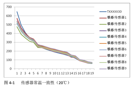
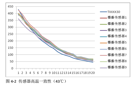
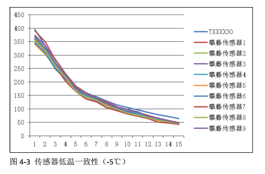
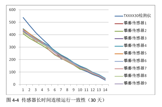
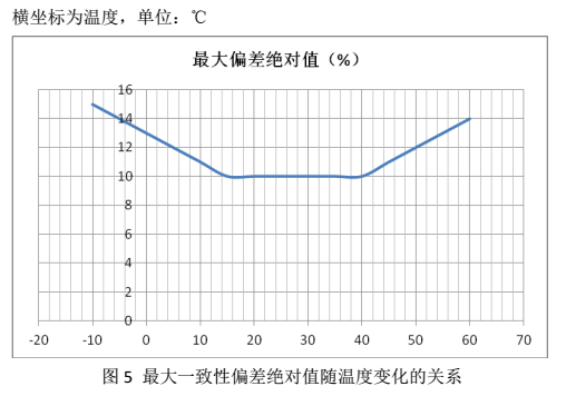
Corresponding relationship between temperature and consistency
Instruction Manual
Open valves, allow air to flow, air is filtered to detect PM2.5 and PM10 values, electromagnetic valves 1 open, electromagnetic valves 2 and 3 remain closed. Then the gas pump power is turned on and the sensor 1 power is turned on. Preheat is required for more than 30 seconds. After testing of dust concentrations in air, a data reading request is sent every second, 60 data are collected for average calculation, the data is the average of minutes and stored at the corresponding location. When the data request is received to the upper-placer, the corresponding data is sent upon request. The SPM CPM data is the product of PM10 CPM data and K values. When the electromagnetic valve 3 is turned on, the power supply to sensors 1, sensors 2 and pumps remains at this level for more than one minute. After closing the pumps for about 15 seconds, a one-minute determination is made that the BG data are tested for more than 10 steps above, until the test result BG data is less than 10, the next step is taken; Disable EMP3. Open electromagnetic valve 1, electromagnetic valve 2. Open the gas pump. In 15 seconds, the determination of sensor 1 and sensor 2 data is started. Continuous testing takes three minutes. Adjusts the average minute value data for sensor 2 based on the average minute value of sensor 2. Performs data measurement for sensors 1 and 2 for one minute. If the error between the two is within 10%, the adjustment is completed, the instrument enters the measurement mode. If the error between the two is more than 10%, repeats the steps required. If three steps 17 do not achieve a 10% error, the adjustment is abandoned, and the output test failed. The measurement mode, turn off EMP2 and Sensor 2, EMP1 and Sensor 1, remain operational, and EMP3 is closed.
When used, attention should be paid to the safety of use and to the need to ensure that it is used in a safe and effective environment.