
An innovative indoor robotic navigation method is based on beacons and PSD research summaries. In this paper, innovative indoor navigation methods have been proposed to meet robotic navigation systems...
An innovative indoor robotic navigation method based on beacon and PSD research
Abstracts. In this paper, innovative indoor navigation methods have been proposed to meet the challenges of robotic navigation systems. Robotic navigational methods typically include visual-based approaches, WiFi signals, infrared beacons, ultrasound beacons, etc. The common problems with these methods, however, are inaccurate. In particular, increasing the precision of robotic positioning mechanisms is key to indoor navigation systems. This paper proposes a way of combining internal rotations of external rotating beacon position sensitive devices (PSDs) and installing them in robots. The robot’s position can be accurately calculated by projecting on both sides of the PSD from the external beacon source of two infrared beams. By optimizing rotation time, dividing work areas and integrating information to compensate for errors, the result can be high performance and accuracy. This innovation, which requires fewer computing resources than other generic methods, is easier to achieve because of its low complexity.
1 Introduction
In a variety of contexts, service robots are widely used. Path planning and choice have a significant impact on software performance and on robot availability. To meet the functional needs of service robots, multiple navigation techniques have been studied. Indoor navigation methods can be divided into map-based navigation and map navigation methods. Their core technology is based on location recognition. Many of the existing studies are based on artificial landmarks, such as stripes and colour objects, but the disadvantage of these methods is that they are heavily dependent on specific tasks, which is unrealistic and on many occasions.
In essence, location perception is essential for a robot to navigate autonomously in one room. It can be collected from the internal state, external signals or both. Intra-sensor information can be derived from gyroscopes, accelerators, mileage tables, etc.[1]. The gyroscope can be used to infer the direction of flight, but the shortcomings accumulate wrongly and ultimately mislead the robot. Random drift, temperature changes, analogue circuit noise, and different types of error will make it difficult to reach [2] precisely. For MPU6050, the result is that even robots are static, the gyroscope has the best ability to move at five degrees, with a full range of £2000 dps every 10 minutes. Moreover, the more serious consequence when robots move is that the gyroscope should be corrected on a regular basis. To solve this problem, the compass is selected, although it does not accumulate errors, because of the Earth's magnetic field, but it is susceptible to magnetic field interference, such as iron, mental furniture[3]. Due to its multiple electrical and other performance components, robots are highly magnetically deduced from the Earth ' s magnetic properties and will interfere completely with the results of digital compasses.
On the other hand, the mileage scale can be used to calculate movement distance[4]. Some studies of indoor navigation assume that robotic wheels do not slide and there are no errors. Unfortunately, these preconditions exist only in the virtual world. In reality, the range scale accumulates a rapid error [5]. In most cases, the error originates from factors such as the wheel radius, the gear gap, and there is a major influencing factor.
Because of external navigation signals, the limitations of the above-mentioned problems can be addressed by providing cyclical cumulative error correction. External navigation equipment can be used to provide sonars, laser rangers, buoys, virtual walls, visual analysis, RFID, etc. The measurement precision and algorithm performance are fundamental and core issues. However, if robotics target the market for domestic applications, the costs of production and the negative effects of easy installation will be an unavoidable problem.
In order to overcome the above and to reduce environmental disturbance, we adapt infrared light sources and beams to direct PSD. Overheating damage to PSD flares, the power of infrared light should be properly controlled. Figure 2.
Locally magnified views send the right side of the map. Two laser diodes are installed in a circle, with an angle of thorium, and they send out two lasers, scintillation, and it is vertically in the rim. One dimensional PSD is installed at the receiving end of B, and when the beam is projected on the surface of the PSD, we can calculate the distance of two light spots. Assuming a virtual line between the centres of the two beams, if the virtual line is expected to be at the centre of the PSD, then the centre surface of the PSD at the same distance of its vertical PSD and the two lies of the two beams d, then we can easily calculate the distance L = D / Sin (Cyber 2), which should be carefully selected to meet the size of the PSD and the maximum and minimum detection length.
Figure 2. Infrared beam lighthouse and robot
PSD-based laser distance and azimuth detection. The size and resolution of our selected PSD device is 1 x 15 mm 0.1um, response time 0.8us. The PSD output tracks a very high resolution and hyper-linearity of the mass density of the movement. The optical elements and sensors used increase distortion, which minimizes the search table. Angular changes would be 0.0055 as a result of the impact of the electronic and mechanical parameters of the walk-in. This is d<PW, PW is the width of the PSD. For the selected PSD, the width is 1.5 cm, the largest L will be 9.77 m.
The idea of measuring distance and azimuth is that, in an ad hoc way, the end of the transmission and the side of the receiving side are rotated. One has begun to be measured by light breakers, while the two-beam projectors A and B continue to rotate to the centre of the PSD at the same distance as B and the two scenes. The rotation angle is then recorded at the azimuth. It is also easy because the vertical distance of the line O1O2 to the surface of the PSD.
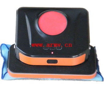
This algorithm can be used to clean robots. One is our prototype: Clean robots. The device describes what will be installed below a square box and a step-by-step generator. The main PCB plate is processed by the ARM processor STM32 and the FPGA chip. The main software is processed, and some of the signal processing functions of the ARM processor are that the FPGA can reduce the impact of real-time processing in the primary processor. At the top of the robot, a large hole, a step-by-step machine is installed in a square box on the step-by-step axis, as shown in figure 8.
Figure 8. Clean robot prototype
7 Conclusion
The PSD, which is driven by a step-by-step machine, is a robot and an external infrared rotation beacon, and, combined with the algorithm described in this paper, the current robot's distance and position beacon can calculate the cycle. Thus, the internal accumulation error can be eliminated. The advantage is that it requires only an external beacon, but also the precision that can be obtained, rather than the expensive components. The content of this is that the step-by-step device is a vulnerable device, which reduces the responsibility of the system.